Configuring Spanning Tree Protocol (STP) Priority
1. Introduction to STP Priority
Spanning Tree Protocol (STP) prevents loops in Layer 2 networks by electing a Root Bridge based on the Bridge Priority and MAC address. The switch with the lowest priority becomes the Root Bridge, making priority configuration essential for controlling the election process.
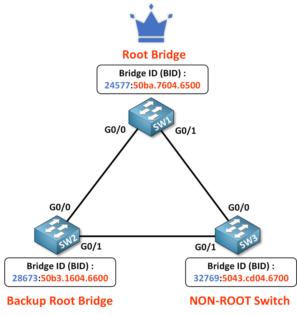
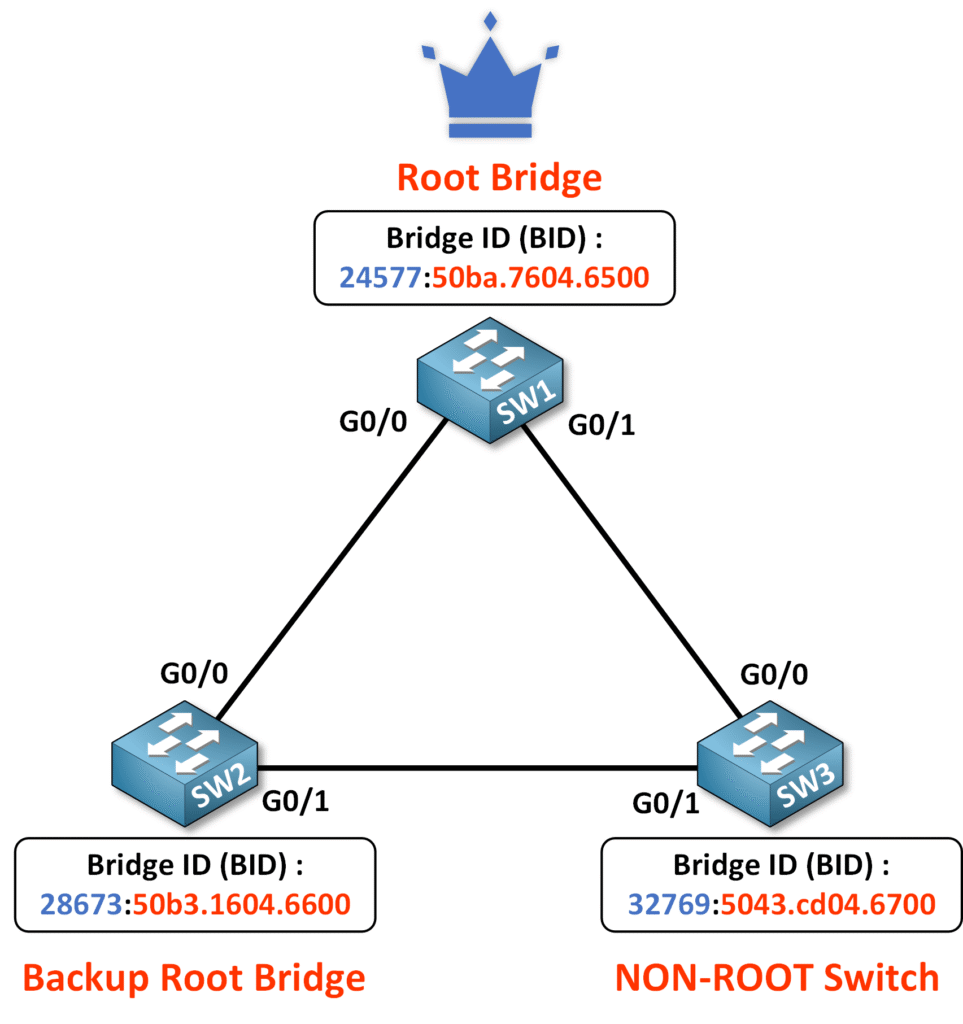
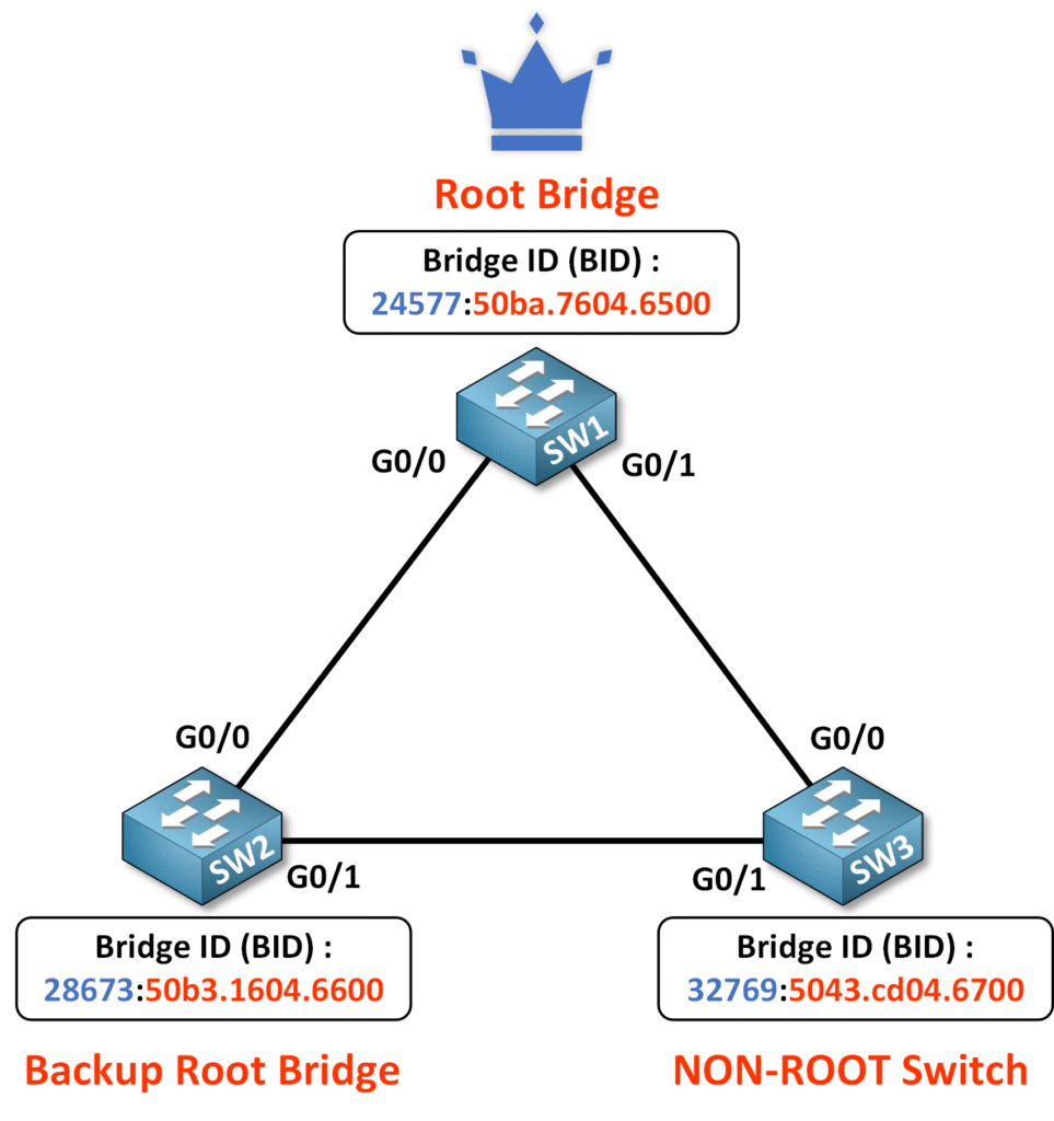
In this guide, we’ll focus on configuring SW1 as the Root Bridge and SW2 as the Backup Root Bridge to ensure a stable, loop-free topology. Let’s dive into the configuration steps.
2. Network Topology Overview
For this configuration, we will use a simple three-switch topology:
- SW1: Intended Root Bridge.
- SW2: Backup Root Bridge.
- SW3: Default priority switch serving as a NON-ROOT switch.

We want to configure SW1 with a low Bridge ID (BID) to ensure it becomes the Root Bridge. SW2 will be set as a backup Root Bridge to take over in case SW1 fails.
Having a backup Root Bridge is a good practice when you want to control which switch will assume the Root Bridge role in the event of a failure. This helps maintain a predictable and stable network topology.
3. Configuring the Root Bridge
Let’s dive into the configuration and get our hands dirty! We’ll configure SW1 to act as the Root Bridge for VLAN 1.
Exploring STP Commands
To start, let’s explore the available spanning-tree commands:
SW1(config)# spanning-tree ?
  backbonefast  Enable BackboneFast Feature
  bridge        STP Bridge Assurance parameters
  etherchannel  Spanning tree etherchannel specific configuration
  extend        Spanning Tree 802.1t extensions
  logging       Enable Spanning tree logging
  loopguard     Spanning tree loopguard options
  mode          Spanning tree operating mode
  mst           Multiple spanning tree configuration
  pathcost      Spanning tree pathcost options
  portfast      Spanning tree portfast options
  transmit      STP transmit parameters
  uplinkfast    Enable UplinkFast Feature
  vlan          VLAN Switch Spanning Tree
Configuring VLAN-Specific STP
Next, we’ll configure STP for VLAN 1, the default VLAN in our setup. To see the available options for configuring VLAN-specific STP:
SW1(config)# spanning-tree vlan 1 ?
  forward-time  Set the forward delay for the spanning tree
  hello-time    Set the hello interval for the spanning tree
  max-age       Set the max age interval for the spanning tree
  priority      Set the bridge priority for the spanning tree
  root          Configure switch as root
Setting Bridge Priority
The Bridge Priority determines which switch becomes the Root Bridge. The valid range for priority is from 0 to 61,440, in increments of 4096.
SW1(config)# spanning-tree vlan 1 priority ?
  <0-61440>  bridge priority in increments of 4096
| Priority Value | Description |
|---|---|
| 0 | Lowest possible priority (highest chance of becoming Root Bridge). |
| 4096 | Very high priority. |
| 8192 | High priority. |
| … | Continues in increments of 4096. |
| 61,440 | Highest possible priority (lowest chance of becoming Root Bridge). |
Note: Using a priority of 0 guarantees the switch has the lowest Bridge ID (BID), making it the Root Bridge in almost all cases.
To set a specific priority:
SW1(config)# spanning-tree vlan 1 priority 0
Using Root Bridge Shortcut Commands
To simplify the process, we’ll use the shortcut command to automatically set SW1 as the Root Bridge. This command ensures SW1 has the lowest priority for VLAN 1:
SW1(config)# spanning-tree vlan 1 root primary
How root primary Works
- If no previous priority is configured, the
root primarycommand defaults the priority to 24,576 + VLAN ID. - If a priority is already configured for the current Root Bridge,
root primaryreduces it by 4,096, ensuring the switch becomes the new Root Bridge.
Verifying Root Bridge Configuration
After configuring SW1, verify that it has become the Root Bridge:
SW1#show spanning-tree vlan 1

VLAN0001
  Spanning tree enabled protocol ieee
  Root ID    Priority    24577
             Address     50ba.7604.6500
             This bridge is the root
             Hello Time   2 sec  Max Age 20 sec  Forward Delay 15 sec

  Bridge ID  Priority    24577  (priority 24576 sys-id-ext 1)
             Address     50ba.7604.6500
             Hello Time   2 sec  Max Age 20 sec  Forward Delay 15 sec
             Aging Time  15  sec

Interface           Role Sts Cost      Prio.Nbr Type
------------------- ---- --- --------- -------- ------------------------
--------
Gi0/0               Desg FWD 4         128.1    P2p
Gi0/1               Desg FWD 4         128.2    P2p
Key Takeaways:
- Default Priority: Without manual configuration, the priority is 24,576 + VLAN ID.
root primary: Reduces priority by 4,096 if a Root Bridge already exists.- Verification: Always use
show spanning-tree vlan 1to confirm the Root Bridge status.
4. Configuring the Backup Root Bridge
Now that SW1 is configured as the Root Bridge, it’s time to set up SW2 as the Backup Root Bridge. This ensures that if SW1 fails, SW2 automatically takes over as the Root Bridge, maintaining a stable and predictable network topology.
Setting SW2 as Backup Root Bridge
To configure SW2 as the backup Root Bridge for VLAN 1, use the following command:
SW2(config)# spanning-tree vlan 1 root secondary
How root secondary Works
- The
root secondarycommand always sets the priority to 28,672 + VLAN ID, regardless of the existing Root Bridge priority.
Verifying SW2 Configuration
Once the configuration is complete, verify the changes using:
SW2# show spanning-tree vlan 1
VLAN0001
  Spanning tree enabled protocol ieee
  Root ID    Priority    24577
             Address     50ba.7604.6500
             Cost        4
             Port        1 (GigabitEthernet0/0)
             Hello Time   2 sec  Max Age 20 sec  Forward Delay 15 sec

  Bridge ID  Priority    28673  (priority 28672 sys-id-ext 1)
             Address     50b3.1604.6600
             Hello Time   2 sec  Max Age 20 sec  Forward Delay 15 sec
             Aging Time  300 sec

Interface           Role Sts Cost      Prio.Nbr Type
------------------- ---- --- --------- -------- --------------------------------
Gi0/0               Root FWD 4         128.1    P2p
Gi0/1               Altn BLK 4         128.2    P2p
Key Observations
- Root ID: Confirms SW1 as the Root Bridge.
- Bridge ID: Shows SW2’s adjusted priority (28,672 + VLAN ID).
- Ports: Root Port forwards traffic to SW1, and Alternate Port blocks to prevent loops.
5. Verifying STP Priority Across the Topology
Now that we’ve configured SW1 as the Root Bridge and SW2 as the Backup Root Bridge, let’s verify the setup and ensure the priorities and STP topology are correctly configured.
Verifying on SW1 (Root Bridge)
To confirm that SW1 is the Root Bridge, use the following command:

From the output:
- The Root ID confirms that SW1 is the Root Bridge. The Root Bridge’s priority is 24577 (priority 24576 + VLAN 1), and the MAC address is 50ba.7604.6500.
Verifying on SW2 (Backup Root Bridge)
On SW2, verify that it is set up as the Backup Root Bridge:

SW2#show spanning-tree vlan 1

VLAN0001
  Spanning tree enabled protocol ieee
  Root ID    Priority    24577
             Address     50ba.7604.6500
             Cost        4
             Port        1 (GigabitEthernet0/0)
             Hello Time   2 sec  Max Age 20 sec  Forward Delay 15 sec

  Bridge ID  Priority    28673  (priority 28672 sys-id-ext 1)
             Address     50b3.1604.6600
             Hello Time   2 sec  Max Age 20 sec  Forward Delay 15 sec
             Aging Time  300 sec

Interface           Role Sts Cost      Prio.Nbr Type
------------------- ---- --- --------- -------- ------------------------
--------
Gi0/0               Root FWD 4         128.1    P2p
Gi0/1               Desg FWD 4         128.2    P2p
From the output:
- The Root ID confirms that SW1 is the Root Bridge. SW2 recognizes SW1’s priority as 24577 and MAC address as 50ba.7604.6500.
- The Bridge ID of SW2 shows its priority as 28673 (priority 28672 + VLAN 1), indicating it is the Backup Root Bridge.
Verifying on SW3 (Non-Root Switch)
To confirm that SW3 is part of the topology but is neither the Root Bridge nor the Backup Root Bridge:

To confirm that SW3 is part of the topology but has no Root Bridge role:
SW3#show spanning-tree vlan 1

VLAN0001
  Spanning tree enabled protocol ieee
  Root ID    Priority    24577
             Address     50ba.7604.6500
             Cost        4
             Port        1 (GigabitEthernet0/0)
             Hello Time   2 sec  Max Age 20 sec  Forward Delay 15 sec

  Bridge ID  Priority    32769  (priority 32768 sys-id-ext 1)
             Address     5043.cd04.6700
             Hello Time   2 sec  Max Age 20 sec  Forward Delay 15 sec
             Aging Time  300 sec

Interface           Role Sts Cost      Prio.Nbr Type
------------------- ---- --- --------- -------- ------------------------
--------
Gi0/0               Root FWD 4         128.1    P2p
Gi0/1               Altn BLK 4         128.2    P2p
From the output:
- The Root ID confirms that SW1 is the Root Bridge with a priority of 24577 and MAC address 50ba.7604.6500.
- The Bridge ID of SW3 shows a default priority of 32769 (priority 32768 + VLAN 1).
6. Conclusion
By configuring SW1 as the Root Bridge and SW2 as the Secondary Root Bridge, we have successfully completed the first step of the Spanning Tree Protocol process: electing the Root Bridge.
In the next course, we’ll dive deeper into STP Port Roles to understand how they enable redundancy and loop prevention by completing steps 2 to 4 of the Spanning Tree Protocol process:
- Elect the Root Bridge
- Identify Root Ports
- Determine Designated Ports
- Assign Alternate (Blocked) Ports
This is essential to identify which ports forward traffic, which remain designated, and which are blocked to ensure redundancy without loops. Understanding these roles will allow us to complete the next steps of STP and build a stable, loop-free topology.
