OSI Model
1. Introduction
The Open Systems Interconnection (OSI) Model, established by the International Organization for Standardization (ISO) in the 1980s, was created to serve as a universal reference for how different computer systems should communicate over a network. A key feature of the model is its layered approach, which divides the communication process into seven distinct layers, each handling specific tasks.
However, the OSI Model is used mainly as a reference to understand how network communication works. In practice, the TCP/IP model became the standard used in real-world networks, as it defines the actual protocols used to transfer data between devices.
2. Encapsulation and De-encapsulation
The OSI Model is divided into seven layers, each with a unique role in the communication process.

To understand how data moves across a network, you need to know two important processes: Encapsulation and De-encapsulation.
Encapsulation
When you send data (like a file or message), it moves down the layers of the OSI model on your device (which is the Encapsulation process).
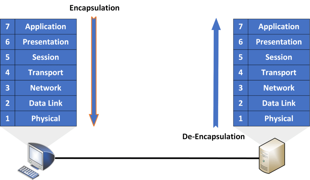
- The Application Layer (Layer 7) starts by creating the data you want to send.
- As the data moves down, some layers add information (like addresses or port numbers) to make sure it gets to the right place.
- At the Physical Layer (Layer 1), the data is converted into signals (like electrical pulses or radio waves) and sent across the network.
De-encapsulation
When the data arrives at the destination, it moves up the layers of the OSI model on the receiving device.
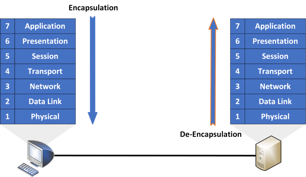
- The Physical Layer (Layer 1) turns the signals back into data.
- The other layers remove the added information step-by-step to check the address and reassemble the data.
- Finally, the Application Layer (Layer 7) presents the original data (like the message or file) to the app you’re using.
Why Encapsulation and De-encapsulation Are Important
- Encapsulation: Ensures the data has the necessary details to reach its destination.
- De-encapsulation: Ensures the receiving device interprets the data correctly and passes it to the correct app or service.
Let’s break down a communication between a source and a destination to show you the OSI model in action !
3. OSI’s Seven Layers
Layer 7 – Application
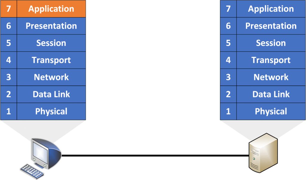
The Application Layer is the closest layer to the end user. It is responsible for interacting with software applications such as web browsers, email clients, and messaging apps. When you attempt to access https://pingmynetwork.com, this layer handles the initial request using the appropriate protocol.
Key characteristics of this layer:
- Closest to the end user: This is the layer where you interact with the network through applications.
- Manages protocols for communication: Examples include HTTPS (secure web browsing), HTTP (basic web browsing), FTP (file transfer), and SMTP (email communication).
Layer 6 – Presentation
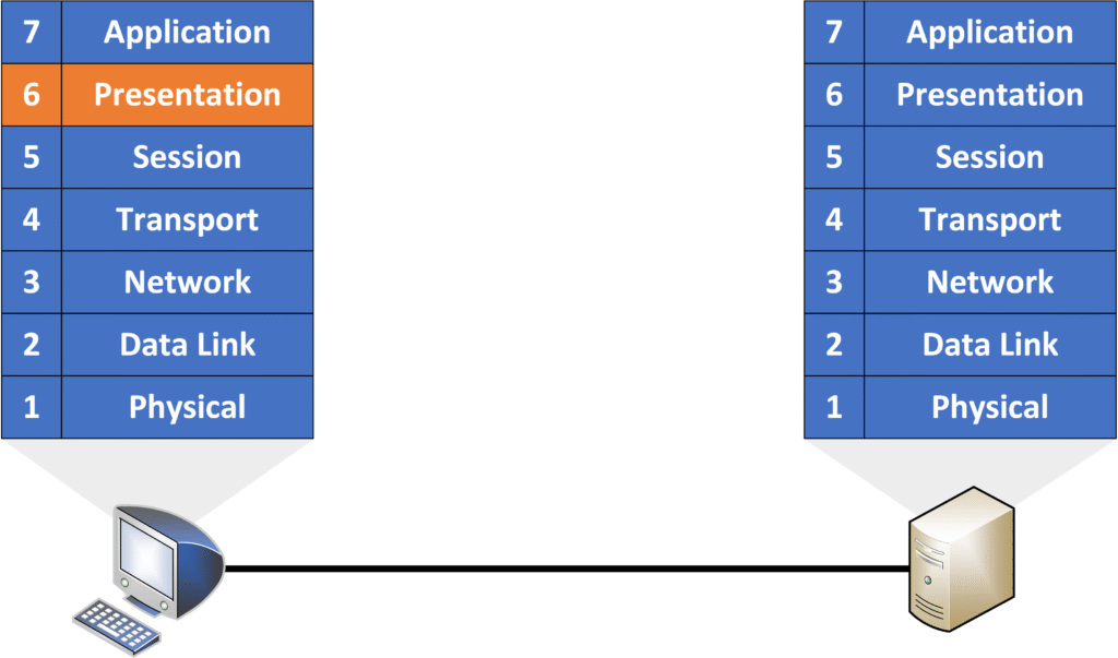
The Presentation Layer ensures that the data is presented in a format readable by the application. It translates data between the application format and the network format.
Key responsibilities:
- Data translation and formatting: Converts data into a format the application can understand.
- Encryption and decryption: Handles secure communication using encryption protocols like TLS/SSL for HTTPS.
- Example: Encrypting data before sending it and decrypting it at the receiving end.
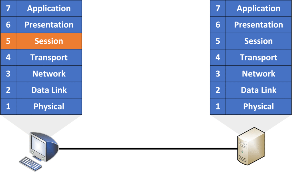
Layer 5 – Session
The Session Layer manages sessions between two communicating devices.
Key responsibilities:
- Session establishment, maintenance, and termination: Ensures that sessions remain active and closes them when communication ends.
- Manages multiple sessions: Supports multiple applications running simultaneously.
Upper Layers
Together, Layers 7, 6, and 5 are referred to as the Upper Layers of the OSI model. These layers are more relevant to software developers, but network engineers must also understand them to troubleshoot communication issues effectively.
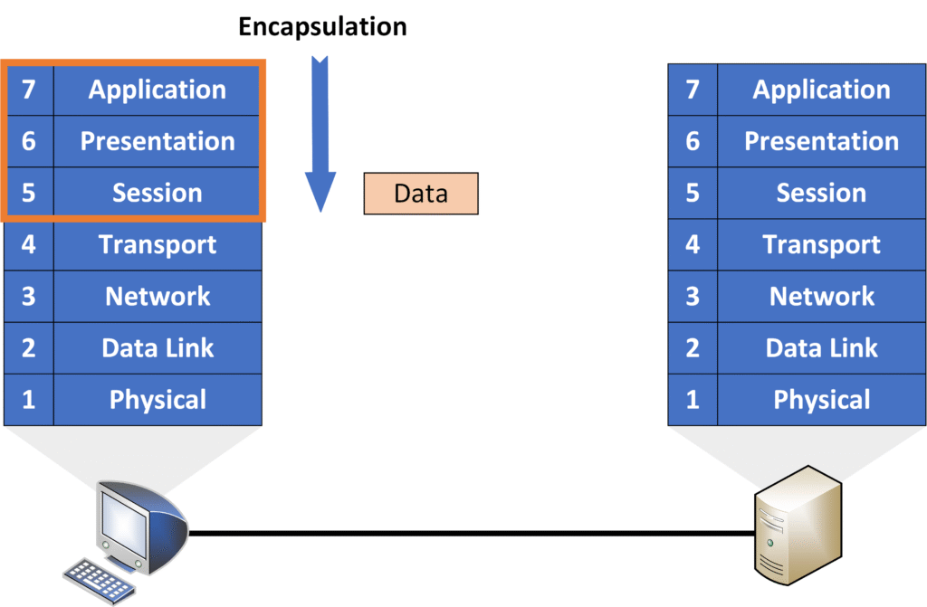
In the top three layers, the data is prepared for transmission. The lower layers (4–1) ensure that the data is sent across the network.
Layer 4 – Transport
The Transport Layer ensures reliable end-to-end communication between devices. At this layer, the data from the upper layers is split into segments, and a Layer 4 header is added.

Key responsibilities:
- Segmentation of data: Breaks large data streams into smaller segments that can be sent over the network.
- Reliable or best-effort delivery: Uses TCP for reliable delivery and UDP for faster, connectionless transmission.
- Host-to-host communication: Identifies specific services using port numbers (e.g., TCP port 443 for HTTPS).
Example:
When watching a long video online, the data is split into segments. If a segment is lost during transmission, the video may lag briefly but will continue instead of restarting.
The combination of the data and the Layer 4 header is called a segment.
Layer 3 – Network
The Network Layer handles the logical addressing and routing of data between different networks.

Key responsibilities:
- IP addressing and routing: Adds the source and destination IP addresses to the data packet and selects the best route for data transmission.
- Packet forwarding: Forwards data from one network to another based on IP addresses.
- Devices: Routers operate at this layer and use IP addresses to make routing decisions.
The combination of a segment and the Layer 3 header is called a packet.
Analogy:
Just like a postal service finds the best path for delivering a package, the Network Layer selects the best route for data to reach its destination.
Layer 2 – Data Link
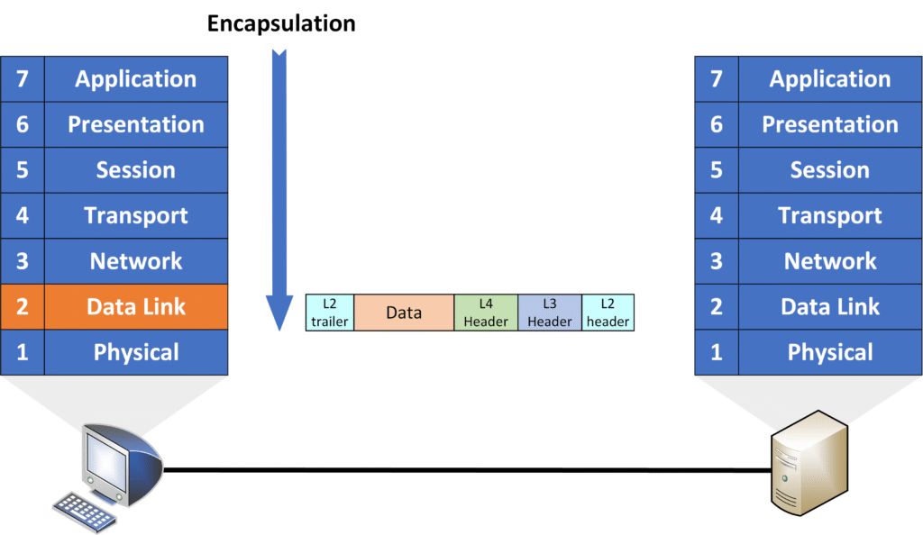
The Data Link Layer is responsible for node-to-node communication within the same local network.
Key responsibilities:
- Framing: Adds a Layer 2 header and trailer, forming a frame.
- Physical addressing (MAC addresses): Uses MAC addresses to identify devices on the same local network.
- Error detection: Adds a Frame Check Sequence (FCS) for error detection to ensure data integrity.
At this layer, the packet becomes a frame. The header includes the source and destination MAC addresses, while the trailer often contains an FCS for error-checking.
Devices:
Switches operate at this layer, forwarding frames based on MAC addresses.
Layer 1 – Physical
The Physical Layer handles the physical transmission of data over the network medium.

Key responsibilities:
- Cables, connectors, and signals: Defines the physical hardware used (e.g., Ethernet cables, fiber optics, wireless signals).
- Bit-level transmission: Converts data frames into bits (1s and 0s) and sends them over the physical medium.
At this layer, the frame is converted into a series of bits and transmitted over the network.
Example:
The Physical Layer is like the road that carries vehicles (frames) to their destination.
Now that we have a complete frame, it is sent from the local device over the Ethernet cable to reach the remote device.
De-encapsulation Process
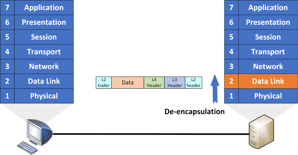
When the data arrives at the receiving device, the reverse process of encapsulation—called de-encapsulation—occurs.
- Physical Layer:
The Physical Layer receives the electrical signals or bits and reconstructs the data to form a frame.

- Data Link Layer:
The Data Link Layer processes the received bits and reconstructs the frame. Once the frame is complete, the layer removes the Layer 2 header (which contained the MAC addresses) and the trailer (which contained the error-checking information).
- Network Layer:
After the Layer 2 header and trailer are removed, the remaining packet (Layer 3) is passed to the Network Layer. This layer removes the Layer 3 header, which contains the IP addresses.

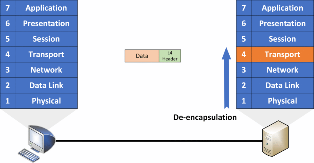
- Transport Layer:
Once the packet reaches the Transport Layer, the Layer 4 header (which contains the port numbers and information for segment reassembly) is removed, leaving only the original data.
- Upper Layers:
The original data is passed up to the Session, Presentation, and Application layers, until it is delivered to the application that requested it (such as your web browser). The data at this point is in its original form, as prepared by the sender.
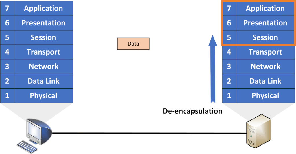
This process ensures that the data is correctly interpreted and presented to the end user.
4. Adjacent-Layer and Same-Layer Interaction
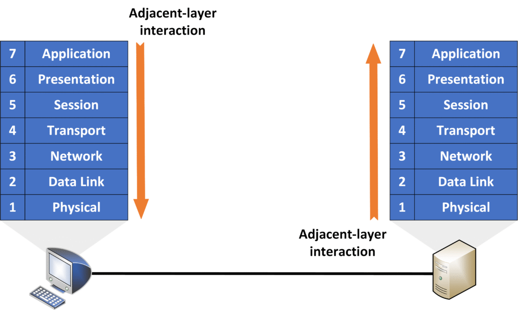
Adjacent-layer interaction
Communication between two layers next to each other on the same device. Each layer passes data to the one below or receives it from the one above.
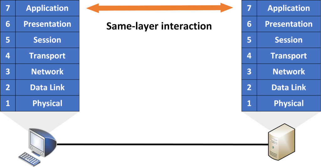
Same-layer interaction
Communication between the same layer on two different devices to ensure the data is correctly understood.
5. PDUs (Protocol Data Units)
When an application wants to send data to another system, it interacts with the Application Layer (Layer 7) of the OSI Model, and the data is prepared for transmission.
As the data moves down the layers, headers (and in some cases, trailers) are added to ensure the information is properly formatted for the recipient. The combination of the original data and the added information forms what is known as a Protocol Data Unit (PDU).
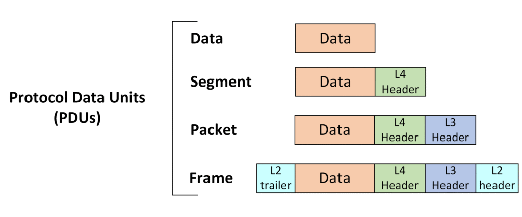
There are multiple types of PDU !
PDU Types Across Layers
- Layer 4 (Transport Layer):
When the Layer 4 header is added, the combination of the data and the header is called a segment. - Layer 3 (Network Layer):
When the Layer 3 header (which includes the IP address) is added, it becomes a packet. - Layer 2 (Data Link Layer):
When the Layer 2 header and trailer are added, it becomes a frame. - Layer 1 (Physical Layer):
At the Physical Layer, the PDU is called a bit, representing the actual binary data being transmitted over the physical medium.
6. How to Remember OSI Layers
Memorizing the seven layers of the OSI Model can be tricky at first, but using simple mnemonics can make it much easier!
Mnemonic from Layer 7 (Application) to Layer 1 (Physical)
“All People Seem To Need Data Processing”
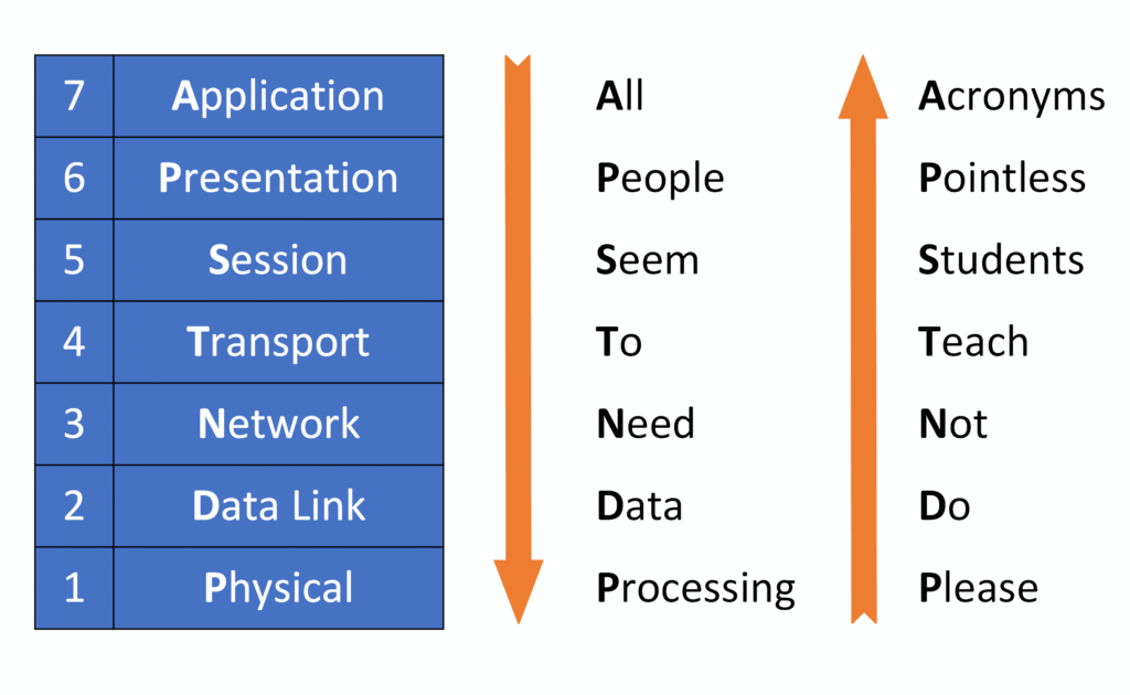
Mnemonic from Layer 1 (Physical) to Layer 7 (Application)
“Please Do Not Teach Students Pointless Acronyms”
In the next course, we will dive into the TCP/IP Model and explore how it complements the OSI model in real-world networking!
